Home > Working with Planning Projects > Building an Application > Model Flow and Linking Models > Using Links (the 'Push' Method)
Using Links (the 'Push' Method)
Last Updated 2/28/2012 12:26 AM
Cascade Planning allows us to define a link or mapping between a source cube and a target cube. This link can either be executed automatically when a user saves a slice of data, or can be executed manually from the MaxiPlan interface, or can be incorporated into a jobset for execution (see Jobsets).
A model cube can link to many other model cubes, and can also have many links from other model cubes. Once defined a link, when executed, will obey the mapping definition defined in the link.
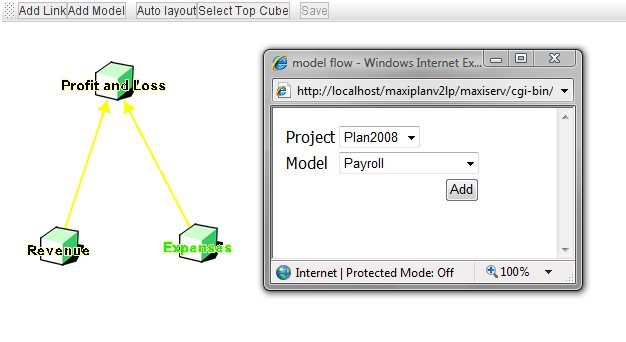
To create a new link or modify an existing link, goto [projectname]->Modeling->Model Flow and the current Model Flow screen will be displayed.
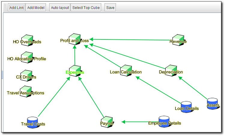
This screen shows the links between the various model cubes and their target model cubes. In our samle above the currently selected model is 'Expenses' highlighted by the green text.
The example shown above is from a reasonably complex suite of models. You can see that the model cube 'Profit and Loss' has multiple links into it from several other models.
Creating a Link
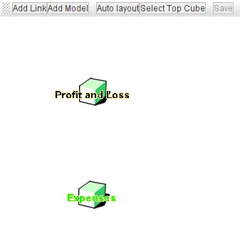
To define a link between a source model and a target model, we need to specify how the various measures, periods and dimensions will map to each other. To illustrate this we will use a simple example, where we wish to link data from our 'Expenses' model to our 'Profit and Loss' model. Model Flow shows the two models in the display.
We firstly select the model we wish to link from by clicking on its icon once. We wish to create a link mapping data from our 'Expenses' model to our 'Profit and Loss' model, so we click on the 'Expenses' model icon once. The 'Expenses' model should be highlighted with green text.
Next, select the Add Link option from the menubar at the top of the Model Flow screen. A yellow arrow will appear between the 'Expenses' and 'Profit and Loss' icons.
Right click the mouse when the cursor is pointing anywhere on the yellow arrow. The arrow will change to a blue colour and a menu will appear.
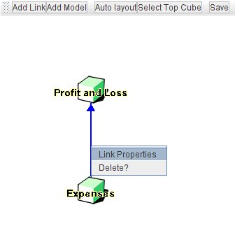
Select the Link Properties option from the menu. This opens a dialogue enabling us to specify the the mapping for the link.
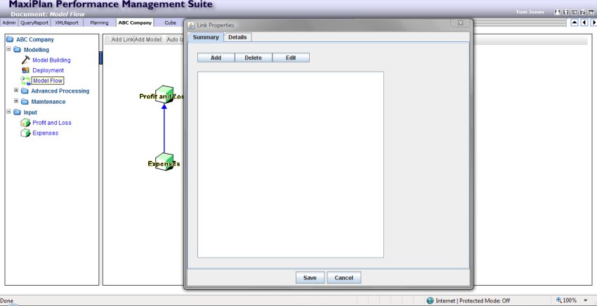
Initially the window will be empty as no linkages have as yet been defined. We can define as many links as we require between the two models, and they will be executed in sequence. This can be useful when we want to create different mappings as we will see in the example later in this documentation.
Before creating the link, let's review what we want to do:
1. The Countries, Versions, and Periods dimensions are the same in both models, and we want the system to dynamically map these, such that the 'Expenses' data for Singapore, Actual, Jan is loaded into the corresponding slice in our 'Profit and Loss' model.
2. The 'Profit and Loss' model has two non-calculation measures: 'Operating Expenses' and 'Non-Operating Expenses'. We want to populate these measures for the corresponding measures in our 'Expenses' model: 'Operating Expenses' and 'Other Expenses' respectively. Any other measures in the 'Expenses' model should be ignored, and any other measures in our 'Profit and Loss' model should remain intact.
The first step in defining the link is to select the Add option from the selection at the top of the Summary tab. This will switch the view to the Details tab, where we can specify the desired mapping.
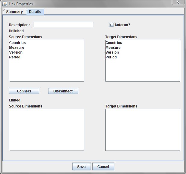
Let's look at the various components of the Details screen.
- At the top of the screen is the Description field. This is compulsory and is the name used to refer to the link we wish to create. The Description can be free form and can containing any alphanumeric characters, blanks and most special characters except '," and /. It is a good idea to use a format that helps identify the link, for example 'Expenses>ProfitandLoss-1' (this identifies a link from 'Expenses' to 'Profit and Loss' and is the first link for these two models.
- To the right of the Description box is the Autorun setting. This is checked by default which means that this link will be executed automatically whenever a model slice is saved or submitted by any user. Also the target model will be recalculated after the link has been executed. You should be careful how you use this setting, and we would advise you to leave this option checked, only if the user who is saving or submitting from the source cube, needs to see the results in the target cube directly after saving.
- The left side of the screen refers to the source model, and initially the top panel shows all the dimensions related to the source model, and the bottom panel shows any dimension from the source model that have been linked.
- The right side of the screen refers to the target model, and initially the top panel shows all the dimensions related to the target model, and the bottom panel shows any dimension from the taregt model that have been linked.
- In between the top panels and the bottom panels are the
 and and  buttons. These are used to define a mapped connection. buttons. These are used to define a mapped connection.
To build a link between any two models the process is simple and straightforward:
- Connect the dimensions you wish to map to each other
- Specify custom mapping for any linked dimensions
- Specify selections for unconnected dimensions
Connecting Dimensions
To connect a dimension in the source model to a dimension in the target model, we simply select the desired dimensions on the left and the right side of the screen (selected dimension will be highlighted in cyan), and then click on the button. The two dimensions will appear in the bottom panels as connected dimensions. In the example below, we have already connected Countries, and we are about to connect the Versions dimension.
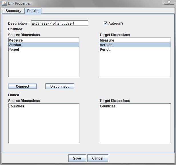
We carry out this step for all the dimensions we wish to map. For our example once we have connected all the dimensions, we should have no remaining dimensions left in the top two panels, because in this particular example, all dimensions are mapped.
Specifying Custom Mapping
In many cases, you may not need to specify custom mapping, since if the dimension member names are the same, the system will dynamically map the source members to the target members, mapping only those member names that occur in each of the source and target dimensions. Connected dimension pairs will be dynamically mapped by default.
However, you may override the default dynamic mapping by specifying the mapping you want to apply to a connected dimension pair. There are a number of reasons why you may wish to do this:
- The member names that you want to map are spelt differently
- You wish to aggregate several memebrs form the source dimension into a single member in the target dimension
- You wish to place a single member from the source dimension into several members of the target dimension
To define custom mapping, in the connections popup window, go to the Linked Source Dimensions panel (the lower left panel), and double click on the dimension name corresponding to the dimension pair you wish to edit. A second popup window will appear.
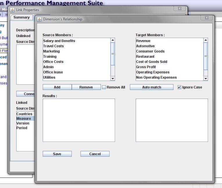
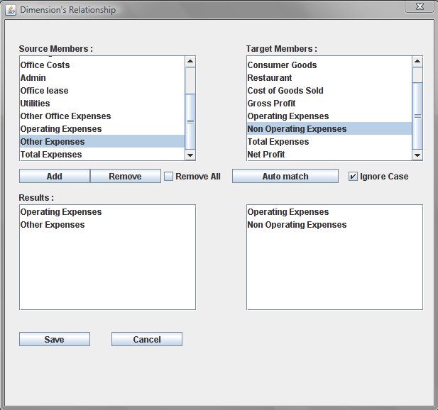
The format is similar to the previous one, except that this time the members of each dimension are listed in the top two panels for the source and target, and the bottom two panels (initially empty) will show the mapped members.
Underneath the two lists of members, the function buttons are:
 |
Selecting this button will add the selected source members and target members to the mapped members in the bottom panels. |
 |
Selecting this button will remove selected members from the lower panel. The  option can be checked to remove all mapped entries from the list. option can be checked to remove all mapped entries from the list. |
 |
Selecting this button will match any member names on the left panel with member names on the right panel. You can uncheck the  option of you wish to ensure that the match is case sensitive. option of you wish to ensure that the match is case sensitive. |
Taking our 'Expenses' to 'Profit and Loss' model, iif we wished to map 'Operating Expenses' on the source side with 'Operating Expenses' on the target side, we could do this by selecting the option. If any other members are mapped that we do not wish to map, we can remove the mapping with the option.
To map 'Other Expenses' on the source side with 'Non Operating Expenses' on the target side, however, we need to do this manually. We do this by selecting the member 'Other Expenses' in the top left panel (it will be highlighted in cyan), and similarly select 'Non Operating Expenses' in the top right panel (similarly highlighted in cyan), and then click the button, and the mapped members will appear in the lower two panels.
If you wish to aggregate data from multiple members on the source side to a single member on the target side, select all the members on the top left panel (you can hold down the CTRL key whilst selecting each member with the mouse, or use the SHIFT key with the mouse to select a range of members), then select the single member on the right panel, and then click the button. In the lower panels you will see the target member repeated for each selected source member. When the link is executed, the source members will be aggregated into the target member.
Conversely, you can map a single source member to multiple target members. The process is the same as above, except that we select multiple target members instead of multiple source members, and we select a single source member rather than mutiple source members. When the link is executed, the source member data will be replicated to each of the target members.
Be careful using this capability. Whilst it can be a powerful and flexible feature, you can potentially create incorrect results with wrongly defined linkages, since if you incorrectly map a source member to multiple target members you could create a 'double counting' problem. Make sure you verify your model links carefully and test the flow of data between the models.
After you have defined any custom mapping for a connected dimension pair, remember to save the custom mapping by selecting the 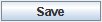 button at the foot of the popup window. If you do not wish to keep the custom mapping, then select the button at the foot of the popup window. If you do not wish to keep the custom mapping, then select the  button. button.
Specifying Selections for Unconnected Dimensions
In the example we have used, we have the same number of dimensions on each side of the link, and the source dimensions can be connected to its corresponding target dimension easily. However, we will not always have the same number of dimensions for the source and target models, and even if the number of dimensions is the same on each side, they may not all be linked.
When this occurs, we may be left with one or more dimensions listed in the unconnected source and target list panels.
If we have an unconnected dimension on the source list, we can select which member(s) we want to use. If nothing is selected, then all the members of the unconnected source dimension will be includede (aggregated).
If there is an unconnected dimension on the target list, we can select which members(s) will be updated by the link. If nothing is selected, then all members of the unconnected target dimension will be updated.
To select the desired members of an unconnected dimension, just double click on the unconnected dimension name in either the source panel or the target panel, and a popup window will appear displaying the list of members in the unconnected dimension.
Using the mouse, select the member(s) desired, and click the button. Click the button if you do not wish to save the selection(s).
Let's look at an example of this requiring a more complicated link definition that the previous example.
Our 'Revenue' model has 'Countries', 'Version', 'Periods' and 'Measures' dimensions as has our Profit and Loss dimension, but 'Revenue' has an additional 'Divisions' dimension.
The Divisions dimension contains the following members:
All Divisions
Automotive
Consumer Goods
Restaurants
The measures in the Revenue model are:
Revenue
COGS
Gross Profit = Revenue - COGS
We want to map our 'Revenue' measure to 'Revenue' in our 'Profit and Loss' model, the measures for which look like this:
Revenue = Automotive+Consumer Goods+Restaurant
Automotive
Consumer Goods
Restaurants
Cost of Goods
Gross Profit = Revenue-Cost of Goods Sold
Operating Expenses
Non Operating Expenses
Total Expenses = Operating Expenses+Non Operating Expenses
Net Profit = Gross Profit-Total Expenses
There is a complication here in that the 'Revenue' is actually broken down by Division within the Profit and Loss Measures, so we will need to map the 'Division' dimension in our 'Revenue' model with the 'Measures' dimension in our 'Profit and Loss' model, for just the 'Revenue' measure in our 'Revenue' model.
Whereas for the 'COGS' measure in our 'Revenue' model, we want to map this to the 'Cost of Goods Sold' measure in our 'Profit and Loss' model, for 'All Divisions'.
We can only connect a dimension to another dimension once in a single link, so if we map 'Division' in 'Revenue' to 'Measure' in 'Profit and Loss' to correctly map the Revenue, we will not be able to map 'Measure' in 'Revenue' to 'Measure' in 'Profit and Loss' to correctly map the Cost of Goods Sold.
The answer to this problem is to define two separate links. We can define as many links as we wish, and each link will be run sequentially after the other within the same link specification.
For the first link, which we will handle the mapping for the 'Cost of Goods Sold':
- Add a new link called 'Revenue>PNL-1'
- Connect 'Countries' to 'Countries'
- Connect 'Versions' to 'Versions'
- Connect 'Periods' to 'Periods'
- Connect 'Measures' to 'Measures'
- Double Click on the connected 'Measures' dimensions from the connected dimensions list, and manually map the 'COGS' measure on the source list to 'Cost of Goods Sold' on the target list.
- Double Click on the unconnected 'Divisions' dimension, and select the 'All Divisions' member, and save the selection.
Now for the second link, which will map each division's revenue to the relevant measure in 'Profit and Loss'
- Before clicking the SAVE button, just select the 'Summary' tab, and click the ADD button again to add a second link (note if you have already clicked the SAVE, just edit the link properties again to add the second link). This link we will call 'Revenue>PNL-2'
- Connect 'Countries' to 'Countries'
- Connect 'Versions' to 'Versions'
- Connect 'Periods' to 'Periods'
- Connect 'Divisions' to 'Measures'
- Double click on the connected 'Divisions'/'Measures' dimensions from the connected dimensions list, and map 'Automotive' to 'Automotive', 'Consumer Goods' to 'Consumer Goods'. and 'Restaurants' to 'Restaurants' (you can use Automatch to do this).
- Double click on the unconnected 'Measures' dimension, and select the 'Revenue' measure, and save the selection.
We have now created two links that will ensure the 'Revenue' is correctly allocated to each division within the 'Profit and Loss', and the 'Cost of Goods Sold'measure in the 'Profit and Loss' model will contain the 'All Divisions' total of 'COGS' from the 'Revenue' model.
Saving the Link
After specifying the link definitions between models, you must remember to click the SAVE menu item on the Model Flow toolbar, to ensure all the linkage specifications are saved back to the server. If you do not click SAVE and try to access another part of the system, you will be prompted to save the linkage changes. If you do not confirm that you wish to save the changes, all definitions created or modified in the session will be lost.
Editing and Existing Link
To edit a previously defined link specification, just right click on the yellow arrow in Model Flow, connecting the models, which will display the link definition editor again and you can make changes as necessary, using the same approach as defined above.
Other Model Flow Functions
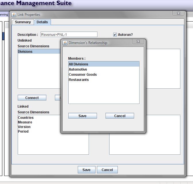
Select Top Cube
Clicking on this option on the Model Flow menubar, allows you to specify an apex or top cube. You shouldnot use this option if you have already specified a custom layout, since the feature will execute the Auto Layout feature immediately afterwards (thus losing any custom layout you have created).
To use this feature, select the option from the menubar, and a popup will apear with a dropdown list of the models in the project. Select the model you wish to be the apex, and then click OK to save the setting.
Changing the Layout
You can modify the layout of the Model Flow. To move a model to a different position on the screen, select the model you wish to move, and then whilst holding the left mouse button down, drag the model icon to the location you desire.
You can also change the layout using the Auto Layout feature on the Model Flow menubar. Selecting the 'Auto Layout' option will attempt to layout the models under the apex defined using Select Top Cube. Note that this method is not really suitable for a really complex layout, as there may be more than one apex in the project.
Linking to a Model in Another Project
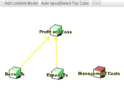
You can link to a model from another project, but first it is necessary to include this into Model Flow. To add a model from another project, select the 'Add Model' option from the Model Flow menubar, and a popup window will display from which you can select the project and the model you want to add to Model Flow.
Once added, the model will appear in Model Flow, as any other model, except that it will be coloured red, instead of green. You can now build links from the added model to another model within the project. Note however that you cannot build a link to that model as a target, as you are not the owner of that model, and do not have the necessary access rights.
Additional Mapping Functions
When linking cube models the mapping between dimensions is fairly straightforward, since it is likely you have designed models using similar dimensions, and thus the dimension member names can be easily matched.
However when we link a transactional model to a cube model, we can run into some matching problems, firstly with date fields, and secondly because we do not know what values are going to be entered into the transaction model, so we cannot define the mapping beforehand.
Fortunately Cascade Planning provides special functions to overcome these problems.
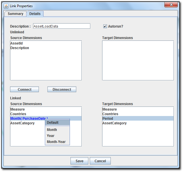
For example if we are using a date field in a transactional model, typically when we map that to our cube model, the period dimension in the cube model may only have a month or a month and year.
To dynamically map the transaction model date field with a cube model period dimension containing only month or only year or month and year, first connect the two dimensions as described above, and then in the left linked source list, right click on the date field, and from the menu list select either MONTH, YEAR or MONTH-YEAR as the format. The date field will be highlighted in blue with the format requested.
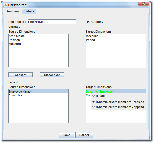
A second problem occurs when need to map a field to a dimension, but we do not know in advance what the field will contain. For example, I may have a payroll model with Employees as a dimension. However I don't know who the employees are until the data has been entered into a transactional model. What I require is the ability to dynamically create the members in my employees dimension from the data being linked from my transactional table.
Cascade Planning provides a means of doing this. Again connect the two dimensions you wish to map, for example Employee Name on the source side, and Employees on the target side. Next right click the dimension name in the list of linked target dimensions, and you can select either 'Dynamic create member – replace' or 'Dynamic create member – append'. The difference between both option is, that 'Dynamic create member – replace will replace/update the dimension. This includes deleting members that no longer exist on the source dimension. On the other hand, 'Dynamic create member – append' will only add new member to the target dimension. When selecting either option, the colour of the dimension name will change to green and will be shown as 'Dynamic (Dimension Name)'. And whenever the link is run, it will automatically create the dimension members in the target dimension.
Note that when you create the target dimension in the cube model, you will need to create at least one member, as a dimension cannot exist without at least one member. You can create the dimension with a member called 'Top Member'.
See also
Cross Referencing (the 'Pull' Method)
|


 Page URL: